Communication Models and Network Topologies Explained
A beginner-friendly guide to understanding communication models OSI, TCP/IP and network topologies.
Communication Models and Network Topologies Explained
Overview
Modern network communication is built upon structured models and topologies that ensure interoperability, scalability, and reliability. Understanding these foundational concepts is crucial for designing, maintaining, and troubleshooting networks. This post delves into the technical details of the OSI and TCP/IP communication models, as well as the most common network topologies, highlighting their structure, function, and practical implications.
Communication Models
Addressing and Protocols
- Multiple Addresses: Each networked device can possess several addresses (e.g., MAC, IP), each associated with a specific protocol or network function.
- Layered Approach: Communication models are organized into hierarchical layers, with each layer responsible for a distinct aspect of data transmission.
- Protocol Stacks: Layers are implemented as protocol stacks, where each layer communicates only with its peer layer on another system, ensuring modularity and abstraction.
What is a Protocol?
- Definition: A protocol is a formal set of rules and conventions that define how data is transmitted and received across a network.
- Analogy: Protocols are like social conventions (e.g., handshakes, greetings) that ensure predictable and successful interactions.
- Protocol Mismatch: If two systems use incompatible protocols, communication cannot occur, leading to failures or data loss.
OSI Model (Open Systems Interconnection)
- Developed by: International Organization for Standardization (ISO) in the late 1970s.
- Purpose: To standardize network communication functions, enabling interoperability between different vendors and technologies.
- Structure: Composed of seven conceptual layers, each with well-defined functions and associated protocols.
OSI Layers (Bottom to Top)
- Physical (Layer 1)
- Manages the physical transmission of raw bits over a medium (e.g., electrical signals, fiber optics).
- Examples: 10BaseT (Ethernet), 1000BaseT (Gigabit Ethernet).
- Data Link (Layer 2)
- Handles node-to-node data transfer, error detection/correction, and MAC addressing.
- Examples: Ethernet, VLANs, ARP (Address Resolution Protocol).
- Network (Layer 3)
- Responsible for logical addressing, routing, and packet forwarding between networks.
- Example: IP (Internet Protocol).
- Transport (Layer 4)
- Ensures reliable or unreliable data transfer, segmentation, flow control, and multiplexing.
- Examples: TCP (Transmission Control Protocol), UDP (User Datagram Protocol).
- Session (Layer 5)
- Manages sessions, establishing, maintaining, and terminating connections between applications.
- Example: RPC (Remote Procedure Call).
- Presentation (Layer 6)
- Translates data formats, encrypts/decrypts, and compresses data for the application layer.
- Examples: ASCII, JPEG, EBCDIC.
- Application (Layer 7)
- Provides network services directly to end-user applications.
- Examples: HTTP (web), SMTP (email), FTP (file transfer).
Key Points
- Layer Independence: Each layer is modular, allowing for independent development and replacement.
- Protocol Mapping Issues: Some protocols (e.g., SSH, ARP) span multiple layers or do not fit neatly into a single layer, complicating strict adherence.
- Practical Use: The OSI model is primarily a conceptual tool for understanding and troubleshooting network issues, rather than a strict implementation guideline.
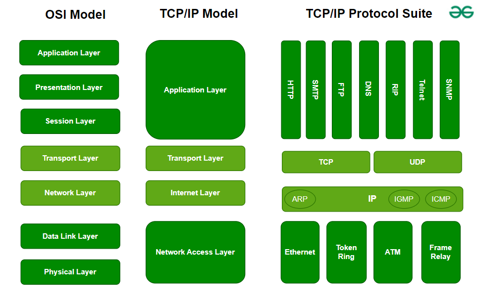
TCP/IP Architecture
- Origin: Developed for ARPANET in the late 1960s and 1970s, forming the foundation of the modern Internet.
- Nature: Describes a practical, as-built protocol suite rather than a purely conceptual model.
- Layers: Consists of four layers, each mapping to one or more OSI layers:
| TCP/IP Layer | OSI Equivalent Layers | Functionality |
|---|---|---|
| Application | Application, Presentation, Session | Application protocols, data formatting, session management |
| Transport | Transport | Reliable/unreliable data transfer, port addressing |
| Internet | Network | Logical addressing, routing (IP) |
| Link | Data Link, Physical | Physical transmission, MAC addressing |
Key Points
- Simplified Structure: TCP/IP collapses the OSI’s seven layers into four, streamlining protocol implementation.
- Protocol Assignment: Protocols are designed to fit specific layers, with clear separation of concerns.
- Industry Reference: While TCP/IP is the dominant protocol suite, OSI terminology is often used for conceptual discussions and troubleshooting.
Network Topologies
Purpose
- Logical Mapping: Network topologies define the logical arrangement of devices and connections, aiding in network design, scalability, and fault tolerance.
- Physical vs. Logical: The physical layout (cabling, hardware) may differ from the logical topology (data flow, communication paths).
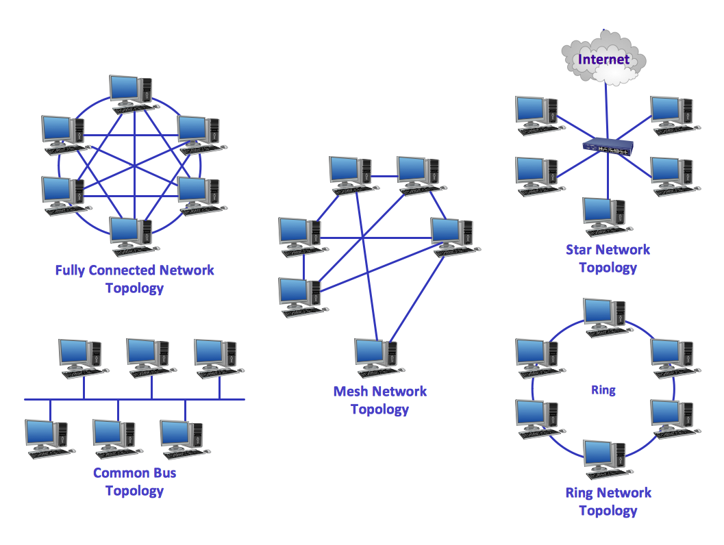
Common Topologies
Bus Topology
- Structure: All devices connect to a single central backbone cable.
- Characteristics:
- No intermediary device; all nodes share the same communication medium.
- Terminators are required at both ends to prevent signal reflection and data corruption.
- Simple and cost-effective for small networks, but prone to data collisions and a single point of failure.
Star Topology
- Structure: Each device connects to a central hub or switch.
- Characteristics:
- Central device manages all network traffic.
- Switches (Layer 2) use MAC addresses to intelligently forward traffic, reducing collisions.
- Hubs broadcast incoming data to all devices, increasing collision risk.
- Offers improved reliability and easier troubleshooting; failure of a single device does not affect the rest of the network.
Ring Topology
- Structure: Devices are connected in a closed loop, forming a logical ring.
- Characteristics:
- Data travels sequentially from one device to the next around the ring.
- Token Ring networks use a token-passing mechanism to control access and prevent collisions.
- No need for terminators; specialized hardware manages signal flow.
- Vulnerable to token loss or duplication, which can disrupt communication.
Mesh Topology
- Structure: Devices are interconnected, either partially or fully.
- Characteristics:
- Multiple redundant paths between devices enhance fault tolerance and reliability.
- Full mesh: Every device connects directly to every other device.
- Number of connections grows rapidly:
n(n-1)/2for n devices. - Complexity and cost increase with network size, but commonly used in wireless and backbone networks for redundancy.
Hybrid Topology
- Structure: Combines two or more topologies (e.g., star-bus, star-mesh) to leverage their respective advantages.
- Characteristics:
- Used to scale networks and improve reliability and performance.
- Example: Star-bus topology connects multiple star-configured switches via a central bus backbone.
- Mesh or ring interconnections can provide additional redundancy.
- More prevalent in physical networks, while virtual networks offer even greater flexibility.
Summary
- Layered Models: OSI and TCP/IP models provide structured frameworks for understanding, designing, and troubleshooting network communication.
- Topologies: The choice of network topology directly impacts performance, reliability, scalability, and maintenance complexity.
- Practical Application: Mastery of both communication models and network topologies is essential for effective network design, optimization, and problem resolution.
This post is licensed under CC BY 4.0 by the author.